How to use the MCP3008-I/P chip to help your Raspberry Pi read digital data from analog sensors
Although your Raspberry Pi is unable to read analog input out of the box, you can get a MCP3008 I/P ADC chip to help your Raspberry Pi do so.
When you connect a MCP3008 I/P chip to your Raspberry Pi, you can read up to 8 analog inputs with SPI.
Given these points, this post will show you how you can use the MCP3008 I/P chip to help your Raspberry Pi read digital data from analog sensors.
Parts used in this tutorial
In case you need it, these are the items that I had used for creating the content in this article:
- Raspberry Pi 4 Model B board
- SanDisk 128GB Ultra microSDXC UHS-I Memory Card
- Solderless Prototype Breadboard
- Breadboard Jumper Wires
- MCP3008 I/P ADC chip
Wiring your Raspberry Pi with the MCP3008 I/P chip
First of all, let's take a look at how we can wire the MCP3008 I/P chip with your Raspberry Pi.
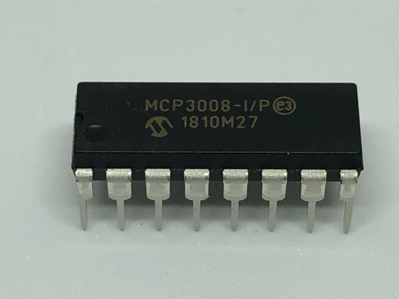
So what is this black piece of plastic with 16 pins?
In order to understand how we can connect the MCP3008 pins with our Raspberry Pi, let's look at the pin reference:
As shown above, with the semi-circle positioned at the top, we have 8 pins to the left and right of the chip.
The 8 pins to the left takes the analog inputs that we wish to read with our Raspberry Pi. You will connect the analog output of the sensor that you wish to readf to one of this pins.
The 8 pins to the right are what we will connect to our Raspberry Pi:
- VDD (Pin 16) to 3.3V pin on Raspberry Pi
- VREF (Pin 15) to 3.3V pin on Raspberry Pi
- AGND (Pin 14) to GND pin on Raspberry Pi
- CLK (Pin 13) to Pin 23/SCLK on Raspberry Pi
- DOUT (Pin 12) to Pin 21/MISO on Raspberry Pi
- DIN (Pin 11) to Pin 19/MOSI on Raspberry Pi
- CS (Pin 10) to Pin 24/CE0 on Raspberry Pi
- DGND (Pin 9) to GND on Raspberry Pi
Given these points, the following diagram depicts how you can connect these 8 pins to your Raspberry Pi:
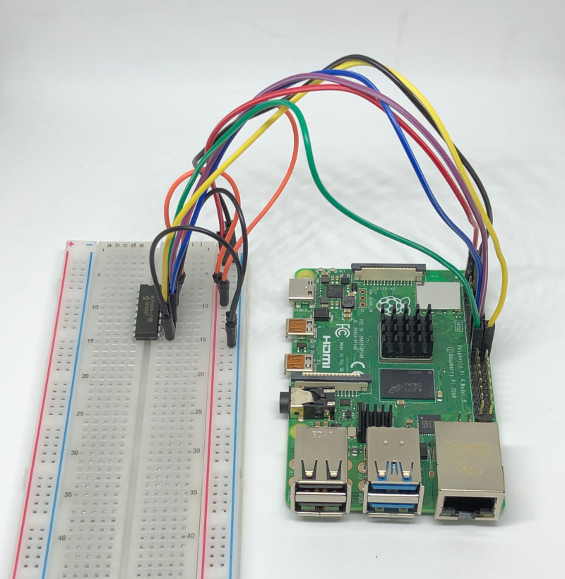
After you have connected the MCP3008 I/P chip to your Raspberry Pi, your setup may look like the following:
Setting up Raspbian to run your Raspberry Pi
At this point in time, you should have already setup a version of Raspbian to run your Raspberry Pi.
If you have not done so, you can follow one of the following articles to help you do so:
- How to setup Raspbian Buster Lite for Raspberry Pi server projects
- How to setup Raspbian Buster for your Raspberry Pi 4 Model B
Enabling the SPI master driver with raspi-config
Once you had setup Raspbian on your Raspberry Pi, enable SPI master driver with raspi-config.
When you had done so, your Raspberry Pi will be able to communicate with the MCP3008 I/P chip.
Setting up a Python 3 virtual environment for reading analog inputs through the MCP3008 I/P chip
Since I am a fan of using Python 3 virtual environments to run applications on a Raspberry Pi, I will show you how to setup the virtual environment for the Python 3 application that we will run later.
With this in mind, let's create the virtual environment with the following command:
python3 -m venv ~/mcp3008-demo-venv
After the command complete, we will have the Python 3 virtual environment located in the ~/mcp3008-demo-venv directory.
Next up, let's activate the virtual environment with the following command:
source ~/mcp3008-demo-venv/bin/activate
Given that, we will be able to install the dependencies that we need for our Python 3 application.
When we wish to read analog inputs through a MCP3008 I/P chip with Python 3, we can use Adafruit's CircuitPython library for MCP300x SPI ADC.
Given that, let's install Adafruit's CircuitPython Library for MCP300x SPI ADC with the following command:
pip install adafruit-circuitpython-mcp3xxx
When the pip installation is successful, you will be able to read analog inputs from your Python 3 script inside that virtual environment.
Sample script to read raw ADC and ADC voltage from analog input connected to first channel of chip
After we had setup the Python 3 virtual environment, let's look at how we can read from one of the analog input with Python.
For example, if we want to read the analog input connected to the first input channel (CH0) of the MCP3008 I/P pin, we can run the following script:
import busio
import digitalio
import board
import time
import adafruit_mcp3xxx.mcp3008 as MCP
from adafruit_mcp3xxx.analog_in import AnalogIn

# create the spi bus
spi = busio.SPI(clock=board.SCK, MISO=board.MISO, MOSI=board.MOSI)

# create the cs (chip select)
cs = digitalio.DigitalInOut(board.CE0)

# create the mcp object
mcp = MCP.MCP3008(spi, cs)

# create an analog input channel on pin 0
chan = AnalogIn(mcp, MCP.P0)

while True:
    print('Raw ADC Value: ', chan.value)
    print('ADC Voltage: ' + str(chan.voltage) + 'V')
    time.sleep(2)
When you run this script, a MCP object is created from the SPI bus that points to the SCLK, MISO, MOSI and CE0 pins of your Raspberry Pi. It then creates an analog input channel that can be used to read the analog input channel on pin 0 of the MCP3008 chip.
After it had setup the channel, it then reads and prints the Raw ADC value and ADC voltage detected at pin 0 every two seconds.
If you wish to read analog inputs connected to other pins on the MCP3008 chip, simply change the second input parameter to AnalogIn.
For example, if I want to read from the analog input channel on pin 7, I will change:
chan = AnalogIn(mcp, MCP.P0)
to
chan = AnalogIn(mcp, MCP.P7)
When I run this script with an analog input connected to the MCP3008 I/P chip, I get the following output:
At this point in time, you should be able to use this setup to read up to 8 analog inputs from your Raspberry Pi. Typically, an analog sensor will have at least 3 pins: +, - and AO. You will attach the + pin to either 5V or 3.3V power source, the - pin to ground and the AO pin to one of the CH0 to CH7 pins on the MCP3008 chip: