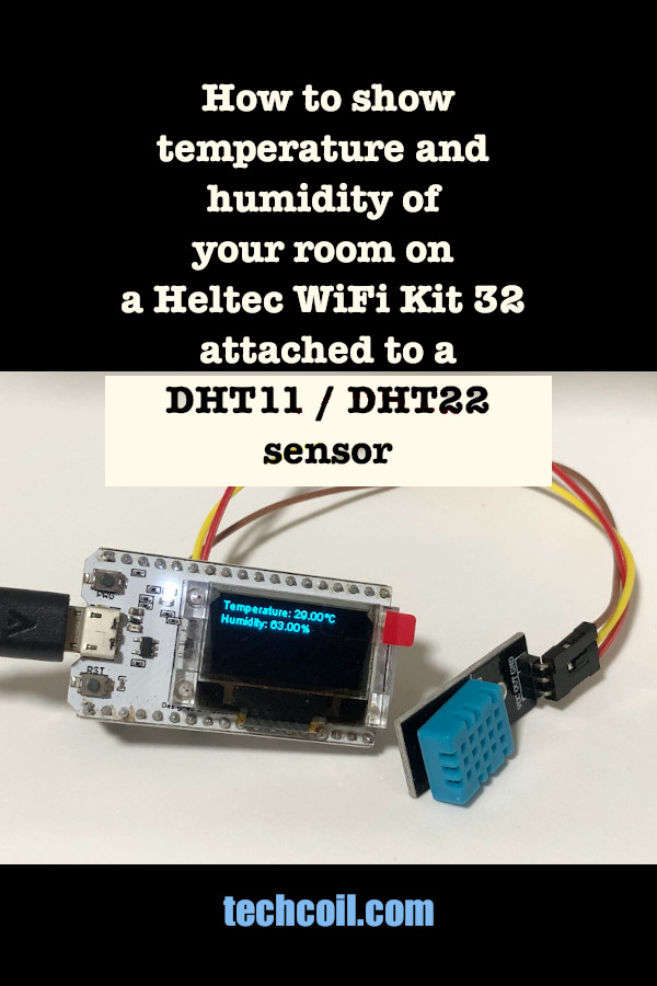
How to show the temperature and humidity of your room on a Heltec WiFi Kit 32 attached to a DHT11 / DHT22 sensor
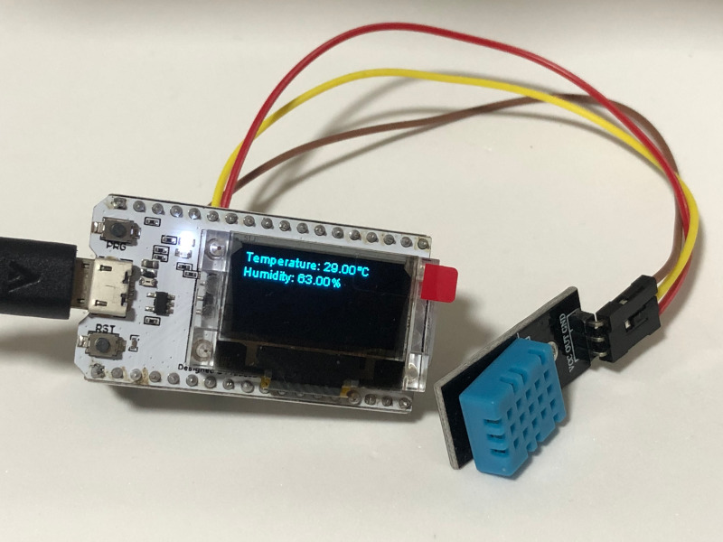
When you have a DHT11 / DHT22 sensor, you can measure the temperature and humidity of your room. If you attach the sensor to a Heltec WiFi Kit 32 development board, you will be able to put up the readings on a 0.96 Inch OLED screen.
Given these points, let's look at how we can show the temperature and humidity readings of your room on a Heltec WiFi Kit 32 development board attached to a DHTXX sensor.
1. Get the hardware to build your thermometer and humidity gauge
First, you will want to make sure that you have the following hardware:
- Heltec WiFi Kit 32 development board
- DHT11 / DHT22 sensor
- microUSB cable
- Soldering iron kit
- Solder wire
2. Connect your DHT11 / DHT 22 sensor to your WiFi Kit 32 development board
After you have gotten the hardware, use your soldering iron and wire to solder the GPIO headers to your WiFi Kit 32 development board.
When you have done so, you can then connect your DHTxx sensor to your development board.
When you look at your DHT11 / DHT 22 sensor, you can see three pins labeled +/VCC, out/s/data and -/GND. Connect the:
- +/VCC pin to a 3v3 pin on your board
- out/s/data pin to GPIO27 on your board
- -/GND pin to a GND pin on your board
For example, if you have a DHT11 sensor, this is how your connection may look like: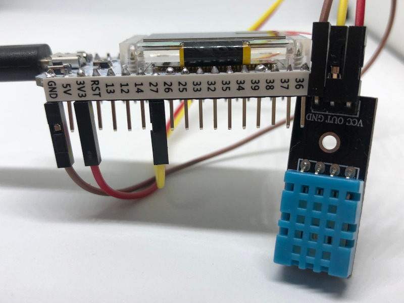
3. Prepare the Arduino IDE environment for ESP32 development
At this point in time, you are ready to flash a program into your ESP32 board to read from the DHT11 sensor. In order to do so, we need to use a tool to write our program into the flash memory of the development board.
Since it is easy to write code and flash programs with Arduino IDE, we can use it to serve our purpose.
In order to use Arduino IDE for this guide, be sure to enable ESP32 development on Arduino IDE before continuing.
4. Install Heltec ESP32 board and Heltec ESP32 Library
Once you have the environment to flash a program to a ESP32 development board, setup Heltec ESP32 board and library on your Arduino IDE.
5. Install the DHT sensor library for ESPx to read temperature and humidity from your DHT11 / DHT22 sensor
In addition to Heltec board and library, you will need to install the DHT sensor library for ESPx to read temperature and humidity from your DHT11 / DHT22 sensor.
In order to do so, first go to Tools -> Manage Libraries.... After you had done so, the Library Manager window will appear. Search for DHT ESPx and install the DHT sensor library for ESPx by beegee_tokyo:
6. Write the Arduino Sketch to read temperature and humidity from DHT sensor and display it on Heltec OLED
At this point in time, you will have everything needed to compose the Arduino Sketch to do what we had intended to do .
In order to read temperature and humidity from DHT sensor and display it on the OLED, we can write the following sketch:
#include "DHTesp.h"
#include "heltec.h"
DHTesp dht;

float currentTemp;
float currentHumidity;

void displayReadingsOnOled() {

  String temperatureDisplay ="Temperature: " + (String)currentTemp +  "°C";
  String humidityDisplay = "Humidity: " + (String)currentHumidity + "%";

  // Clear the OLED screen
  Heltec.display->clear();
  // Prepare to display temperature
  Heltec.display->drawString(0, 0, temperatureDisplay);
  // Prepare to display humidity
  Heltec.display->drawString(0, 12, humidityDisplay);
  // Display the readings
  Heltec.display->display();
}

void setup()
{

  dht.setup(27, DHTesp::DHT11);

  currentTemp = dht.getTemperature();
  currentHumidity = dht.getHumidity();

  pinMode(LED,OUTPUT);
  digitalWrite(LED,HIGH);

  Heltec.begin(true /*DisplayEnable Enable*/, false /*LoRa Enable*/, false /*Serial Enable*/);
  displayReadingsOnOled();
}


void loop()
{
  float temperature = dht.getTemperature();
  float humidity = dht.getHumidity();

  if (temperature != currentTemp || humidity != currentHumidity) {
    currentTemp = temperature;
    currentHumidity = humidity;
    displayReadingsOnOled();
  }

  delay(2000);
}
So what is the sketch doing?
First, we include the DHTesp.h and heltec.h header files that contain the functions that we will need for our sketch.
After that, we create a DHTesp object to interact with the DHT sensor.
Next, we declare currentTemp and currentHumidity to hold float values that represent a set of temperature and humidity readings.
After that, we define the displayReadingsOnOled function that will display the temperature and humidity readings to the OLED.
Inside the displayReadingsOnOled function
First, we construct the Strings that will output the temperature and humidity readings to the display.
After that, we use Heltec.display->clear to clear the contents of the OLED.
Once we have done so, we prepare the screen to display the temperature and humidity readings with Heltec.display->drawString.
Finally, we make a call to Heltec.display->display to show the readings on the OLED.
Inside the setup function
Since the setup function is called once, we use it to run the logic to initialise the resources that we will need.
Given that we first call dht.setup on get the board to read from our DHT sensor at pin 27.
After that, we get the first set of temperature and humidity reading from the DHT sensor.
When we have done so, we use pinMode, digitalWrite and Heltec.begin to initialise the OLED.
Finally, we call displayReadingsOnOled to display the first set of readings to the OLED.
Inside the loop function
Since the loop function is called for as long as the board has power, we use it to run the logic to read from the DHT sensor.
Whenever loop is called, we get a set of readings and compare it with the previous set of readings.
If there is a change in the new set of readings, then we first update currentTemp and currentHumidity with the new values. After that, we call displayReadingsOnOled to display the latest set of readings to the OLED.
Finally at the end of the loop function, we call delay to wait for 2 seconds before reading from the sensor again.
7. Upload the Arduino Sketch to your Heltec WiFi 32 board
Once you have created the Arduino Sketch, connect the microUSB cable to your Heltec WiFi 32 board and computer.
After that, select WiFi Kit 32 as the board to use in your Arduino IDE:
In addition, select the serial port to upload the sketch:
Once you had done so, upload your Arduino Sketch to your Heltec WiFI 32 board:
When your Arduino sketch is loaded onto the Heltec WiFi 32 board, you will get the temperature and humidity readings on the OLED screen when there is power supplied to the board.